
Updated 2024-06-23.
This is a project to automatically power my house with my pair of Ecoflow Delta Pro batteries during a utility outage, which we regularly get here in my part of California.
IMPORTANT DISCLAIMER: I am not an electrician. Electricity can be dangerous and can kill you or burn your house down. The information here is presented with NO WARRANTY and you should consult a qualified expert before trying to do any work on your home’s electrical system.
Welcome to those of you coming from Bunnie’s Name That Ware! See below for more photos of the ware in question.
Electrical panel configuration
I have three electrical panels in my house: a main 200A panel at my service entrance which takes input from my local electrical utility plus my solar panels, and feeds a couple of small circuits. From there it connects to two subpanels in my garage.
The main garage subpanel has most of the circuits in the house, with a 240V 60A breaker that feeds a second subpanel for emergency loads. There is a generator inlet feeding the emergency load panel with an interlock switch to select utility power or generator input. The interlock physically prevents energizing both the utility input and generator input at the same time for safety; you don’t want to backfeed the utility lines where someone might be working on them to repair a power outage.
The emergency load panel is a typical US split-phase setup where all but one of the circuits are on one 120V leg, except for my heat pump water heater which uses 240V. The generator inlet is wired for 240V to feed both legs.

Battery setup
I have two Ecoflow Delta Pro batteries and a double voltage hub that plugs into both batteries and combines them into one 240V output. I intended originally to simply feed 240V from the hub into the generator inlet, but I discovered two problems with this:
- The house circuits in the load panel aren’t very well balanced between the two legs of the 240V input, which seemed to cause the Ecoflow hub to have problems and shut off. However, I haven’t systematically verified this yet under controlled conditions. (I was somewhat desperate when I tried it due to a day-long power outage, and quickly tried the workaround described below.)
- When using the hub, you can’t charge the batteries from 120V, which means I can’t plug them into the 120V output from my Ioniq 5 to extend the running time of the batteries.
Update: it turns out I can charge them from their DC input, so I can use two 120V to 36V power supplies to charge from my car, albeit somewhat inefficiently.
I assume the latter problem is because the combiner synchronizes the two batteries so the two 240V legs have the correct phase between them, and it’s unable to also synchronize them to a 120V input at the same time. Using the DC input gets around this problem.
As a workaround during a recent power outage, I simply split the input to the panel into two separate 120V inputs and shut off the 240V breaker to the water heater. This allowed me to run all my circuits successfully, although I have to be careful not to overload the neutral wire since it’s now carrying all the current from both 120V circuit. In practice I’m using very little power – just lights and my refrigerator – so this wasn’t a concern for me, and going back to using the 240V combiner should fix this.
The process of switching over is currently manual. I have to turn on the batteries, turn off the water heater breaker, and switch the interlock over to the generator input. I’d really like for this to be automatic, but the smart home transfer switch sold by Ecoflow would be really expensive for me since it doesn’t work by default with AFCI breakers. (The problem is that it combines the neutral on all the circuits, which is forbidden for AFCI breakers. You can move them all downstream from the smart panel, but then you’ve got a total of three panels with two sets of circuit breakers and are into it for at least $1600, which all seems pretty ridiculous.)
So, since I think I’m smart, I figured I could roll my own lower-cost solution. The hard part here is getting a beefy relay that can handle at least 100A to switch over from utility to backup power, and also guarantee that it will never bridge the two, just like the manual interlock. I looked at a bunch of high-power contactors, but in the end I decided that just using an existing automatic transfer switch would be a lot safer since it’s already designed to meet electrical codes.
The transfer switch
I bought a Generac RXSC100A3 100A automatic transfer switch, which is designed to interface with a Generac generator, of course. It has two solenoids that switch the power between utility and generator, and guarantees not to bridge the generator onto the utility input. It’s really beefy – it comes in an enclosure that is far bigger than it needs to be, and seems very sturdy.
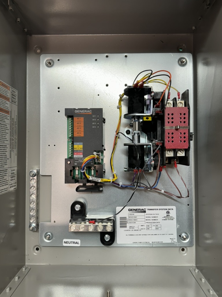
In the photo you can see the logic module on the left, with the solenoids and contractor on the right. (Strangely, there isn’t any knockout for running wiring into the enclosure; I guess you’re supposed to use a knockout cutting tool to do that yourself wherever you want.)
The transfer switch itself does not decide when to switch over – instead, the generator is expected to signal the switch, so that it can have time to start up and stabilize before taking the electrical load. The generator’s battery powers the relays and the transfer switch logic module with a 12V input.
When the generator is ready to throw the switch, it grounds the transfer signal line, which throws a relay in the controller. This energizes the actual transfer switch solenoid, which is powered by the generator 240V input. If the generator isn’t putting out sufficient power then the solenoid won’t throw the switch. There are limit switches on either side to de-energize the solenoid once it moves the contactor to the correct side.
As far as I can tell from the circuit diagram available from Generac, the logic module doesn’t do anything with regard to the actual switchover – it just has the “smart” logic to shed A/C loads when there’s too much draw on the generator. I don’t care about that functionality so I can just concentrate on the actual switching logic.
Here are some more photos of the transfer switch:
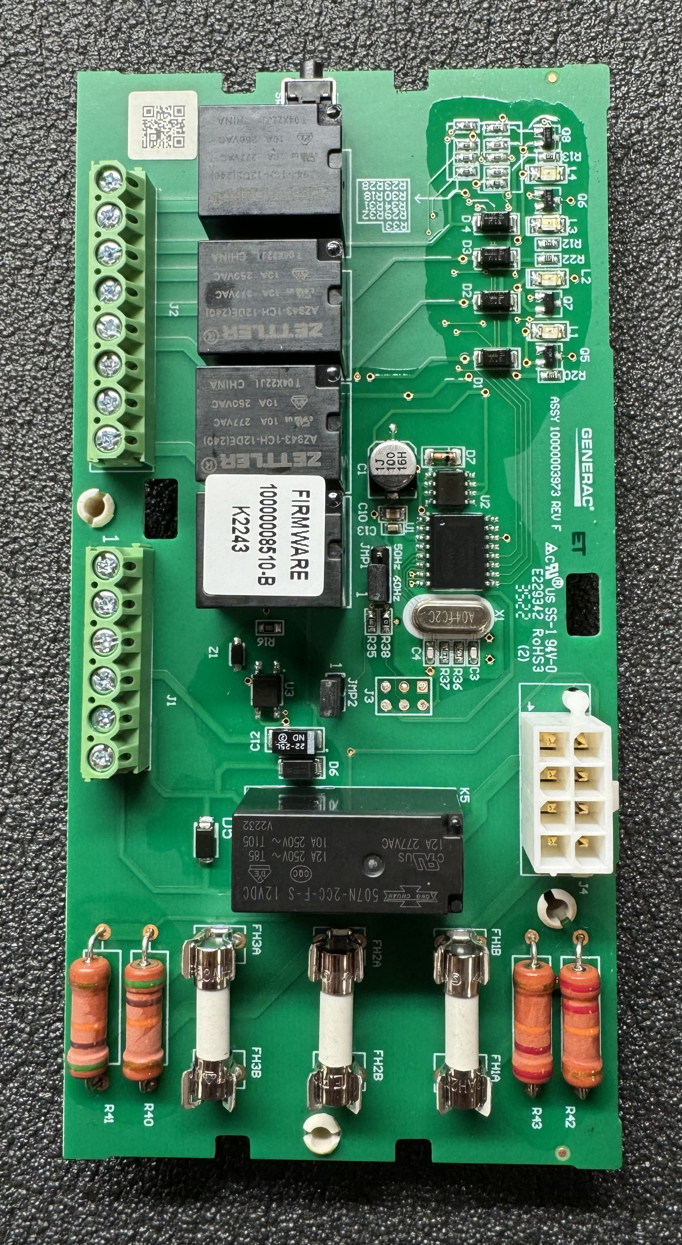
This is the main circuit board; you can see the three fuses at the bottom for the input power, and the terminal block for air conditioner load shedding control on the upper left. The terminals on the lower left are for utility power sensing, 12V input and the transfer control signal.

Here’s the board with the cover on and the terminals labeled. The connector on the right goes to the solenoid and contactor assembly. Nice that they included a fuse puller at the bottom.
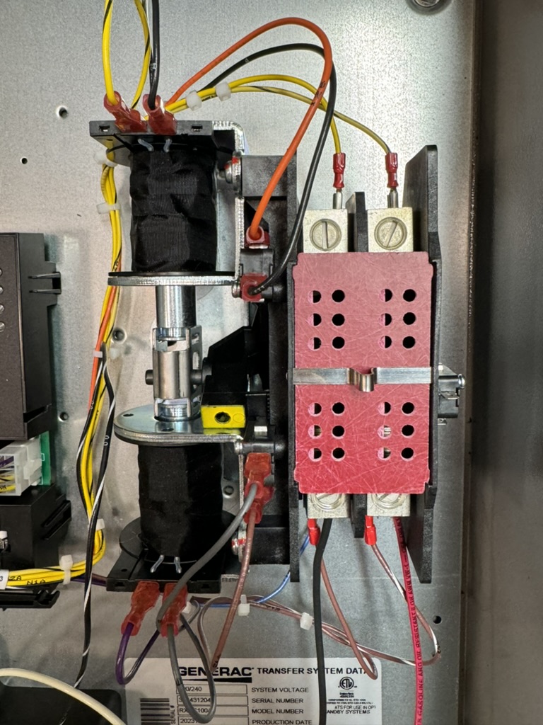
The solenoids are on the left that move the contactor on the right. Utility power comes in the top and the bottom connectors are for the generator supply and load power output.
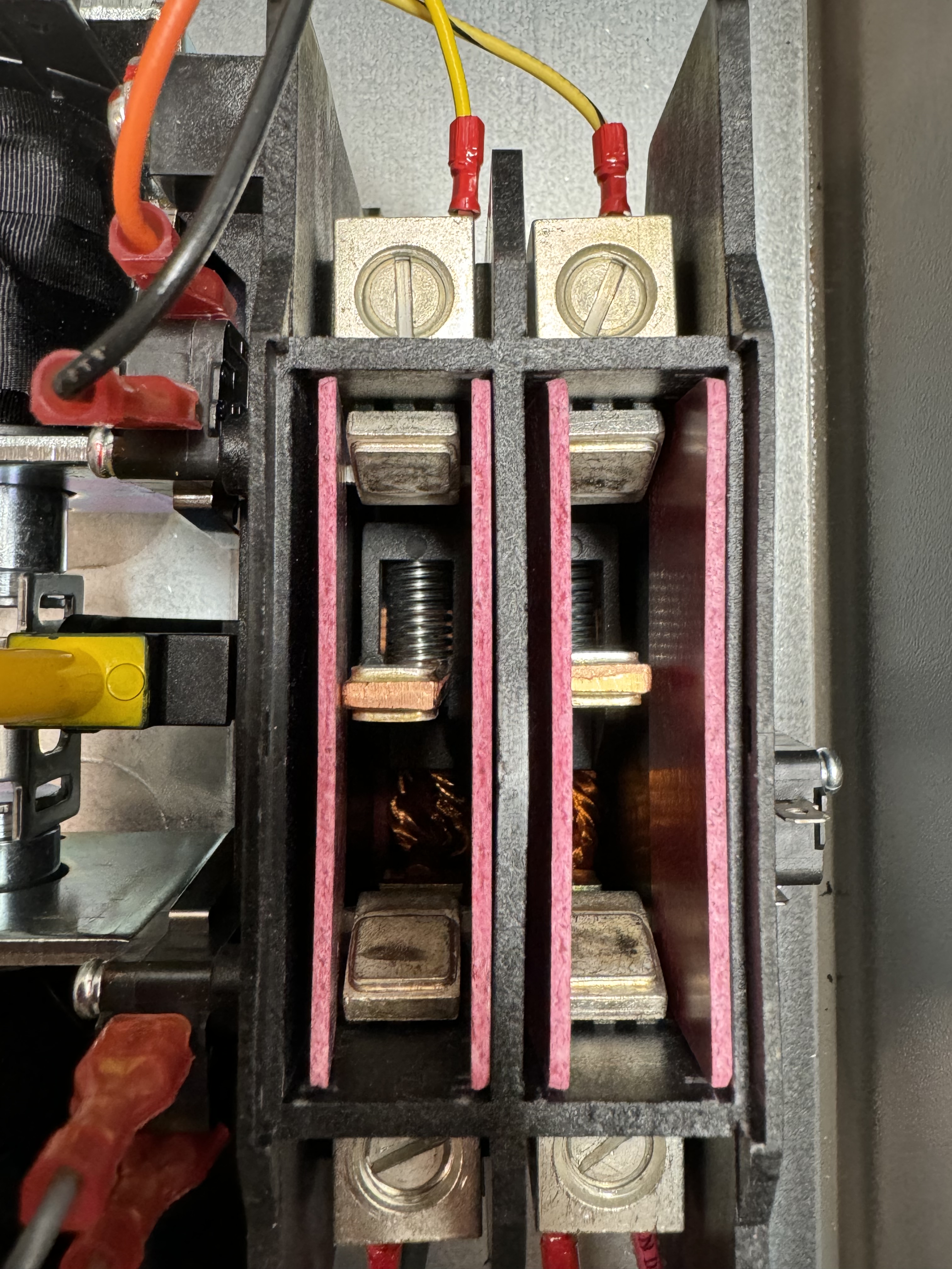
Here’s a closeup of the contractor itself halfway between the two positions with the cover removed. It’s a pretty robust piece of metal! The yellow thing on the left is the lever that lets you flip it between the two positions manually. As you can see, there is plenty of separation to make sure that utility power and generator power will never meet each other.
Logic control
I could have a simple relay that controls the transfer switch and throws it whenever utility power cuts out. However, this isn’t ideal since a momentary voltage drop could trigger the transfer and then switch back again.
We need to debounce the utility power – wait till it’s been out for some period of time, and then turn on the “generator,” and guarantee to leave it on for some minimum period of time even if utility power comes back, to prevent quick cycling.
My plan is to use an Adafruit Feather microcontroller with a voltage sensing module to do the logic. These Feather boards are nice because they have a built-in charger for a LiPo battery that can serve as a tiny UPS to keep the controller running when the utility power goes out; if I want, I can select a battery that has enough juice to run for the debounce period until the big batteries can resupply power to it. The particular Feather board I’m using has wifi, so it can connect to Home Assistant or some other control mechanism if I want it to.
However, since the transfer switch relays need 12V, the Feather’s backup battery isn’t enough, so I need some kind of 12V backup supply to power both the board and the relays and I can forego the LiPo battery altogether.
I first tried a solar battery controller module and small 12V lead-acid battery to use for powering the transfer relay. The controller has USB 5V out that can power my Feather, and I’m using an old 12V wall wart to charge the battery. Unfortunately the battery controller wants a constant-current input like solar panels, and doesn’t do so well with a constant voltage wall wart, so I gave up on that approach.
A better solution was a 9V/12V power supply that has a provision for a 3.7V lithium-ion backup battery. (I had to figure out for myself that it defaults to 9V until you short a jumper on the board.). A small battery is enough to power everything for the 30 seconds or so needed to switch over to backup power.
For detecting when utility power goes out, the voltage sensing module is not as easy to use as I thought – it outputs a DC sine wave shifted to a little less than half of the DC input voltage, so it doesn’t give me a straight on/off voltage signal. I would have to use one of the analog voltage comparators on the Feather to detect the sine wave crossing the offset voltage, or just poll the analog input to see if it’s wiggling.
I decided a simpler option was to just use a USB power supply and detect that going from 5V to zero when power is lost. I used a 5V to 3.3V power supply to do level shifting, and at first this seemed fine – until I turned off power to the Feather and discovered that it was being back-powered through the 3.3V logic input! The solution to that is a PC817 opto-isolator; the board I picked has two channels so I can detect both utility and backup power levels.
The 12V supply is powered by the T1 connection on the transfer switch, which is connected to one 120V leg of either utility or backup power depending on which is currently active, so it will keep the 12V backup battery charged even when on backup power.
Open questions
- Can the microcontroller turn the Ecoflow batteries on, or do they have to be on all the time? Maybe I can hack the power button on the Ecoflow batteries as a simple control mechanism. The batteries actually have an ethernet connection that can be used by a remote control unit, so I may be able to reverse engineer the protocol and control them that way. It’s been a while since I’ve used Wireshark, but that might be fun. Leaving them on all the time would work, since they have a setting that keeps the AC output on continuously, but it does slowly drain the battery which causes it to recharge periodically, which will reduce the battery life over time.
Next steps
Rewire my “generator” input once again to use the 240V output of the voltage doubler.This is done; I added the 30A inlet to the transfer switch housing.Wire up the transfer switch to the emergency load panel.This is done and my house power is now flowing through the switch by default.Try the Ecoflow voltage doubler again to see if it really does have a problem with my house loads. I can measure the draw on each leg to see exactly how unbalanced it is under the load I expect.I did a short test and was able to power the emergency load panel using the voltage doubler.Double-check that I can charge the EcoFlow batteries using the DC input while they are discharging.I verified this works during my voltage doubler test.Wire up the microcontroller for full control of the transfer switch.This is now done; for details see the next blog post.
